
|
|


Risultati da 106 a 120 di 163
Discussione: Sony 1271QM - Lista condensatori elettrolitici
-
23-01-2005, 09:57 #106
 Advanced Member
- Data registrazione
- Dec 2004
- Località
- Bologna
- Messaggi
- 2.236
Io domani sono in un negozio di elettronica a comprare dei componenti per me. Se vuoi evitarti il giro te li recupero io.

800 tutti e tre non è troppissimo dai...non è neanche poco però. Certo che poi avresti un proiettore nuovo di pacca tra tubi e condensatori
Per le lenti come preferisci. Se non è un problema faccio un salto io domani. Se devi sbatterti rimaniamo per mercoledì, no problem.
-
23-01-2005, 17:42 #107
Senior Member
- Data registrazione
- Aug 2003
- Località
- Fombio (Lodi)
- Messaggi
- 515
Ciao Edo,
se riuscissi a recuperare i componenti sarebbe grande, ti avrei proprio chiesto una indicazione di un buon negozio su Bologna. Domani ho una giornata molto strana, in pratica mi muovo per fare un brindisi alle 17.30 ed in mattinato avevo intenzione di cercare i componenti per la riparazione e magari i condensatori non polarizzati (oltre ai 3 10uF 350 V che chiaramente devo sostituire ). Portare le lenti non è un problema, con consegna o in mattinata o dopo le 18.30/19 ... chiamami pure sul cellulare per farmi sapere come preferisci e ci mettiamo d'accordo.
I tubi sono effettivamente andati, purtroppo Plexi47 ha avuto un problema analogo sui suoi 9" ed è stato facile rendersi conto che abbiamo entrambi bruciato i fosfori, io al centro con un puntino e lui con una bella riga . Rischi del "mestire".
Se riusciamo a riparare l'elettronica i tubi mi sa che li sostituisco da solo, Mauro si è detto disponibile a darmi una mano e se Edo vuoi raggiungerci facciamo uno squadrone ed aggiungiamo una nuova sezione al sito
Ciao
MicheleUltima modifica di mcito; 23-01-2005 alle 21:32
Un tipo come me si incontra una volta sola ... se hai sfiga due !
-
23-01-2005, 19:49 #108
Advanced Member
- Data registrazione
- Dec 2004
- Località
- Bologna
- Messaggi
- 2.236
Domani faccio il giro e vedo che trovo da radio ricambi.
Per beccarci direi che è meglio verso sera così faccio tutti i giri di mattina.
Le molle per la modifica alla fine le usa il tuo amico o le ha scartate?

Mi dispiace per i tubi. un vero peccato anche perchè erano praticamente nuovi
Ah una cosa...magari dalla maxivideo quando li contatti per i tubi potresti sentire se hanno il glicole e il silicone per i crt che sto ancora aspettando la risposta? Grazie mille
Ora scappo che star wars ep. 2 mi aspetta
Ciao, a domani.
-
23-01-2005, 21:34 #109
Senior Member
- Data registrazione
- Aug 2003
- Località
- Fombio (Lodi)
- Messaggi
- 515
Ok per la serata, ti porto anche le molle visto che il mio amico preferisce lasciare stare le modifiche (tu hai ancora i distanziali M, sarebbero utili per la sua installazione).
Ciao e a domani
MicheleUn tipo come me si incontra una volta sola ... se hai sfiga due !
-
24-01-2005, 08:06 #110
Advanced Member
- Data registrazione
- Dec 2004
- Località
- Bologna
- Messaggi
- 2.236
Perfetto grazie mille.mcito ha scritto:
Ok per la serata, ti porto anche le molle visto che il mio amico preferisce lasciare stare le modifiche (tu hai ancora i distanziali M, sarebbero utili per la sua installazione).
Ciao e a domani
Michele
Spero di riuscire a smontare i distanziali in giornata così te li porto stasera.
Mo faccio la lista della spesa e vado da radio ricambi
-
24-01-2005, 12:07 #111
Senior Member
- Data registrazione
- Aug 2003
- Località
- Fombio (Lodi)
- Messaggi
- 515
Q41 - Caratteristiche
Un tipo come me si incontra una volta sola ... se hai sfiga due !
-
24-01-2005, 12:26 #112
Advanced Member
- Data registrazione
- Dec 2004
- Località
- Bologna
- Messaggi
- 2.236
La sfiga è che è un bjt ad alto guadagno. Non sono facilissimi da trovare con quei parametri purtroppo.
Ora cerco..
-
03-02-2005, 20:34 #113
Advanced Member
- Data registrazione
- Dec 2004
- Località
- Bologna
- Messaggi
- 2.236
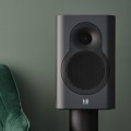
Una foto dei condensatori cambiati fin'ora


In foto sembrano la metà
-
04-02-2005, 05:48 #114
Advanced Member
- Data registrazione
- Dec 2002
- Località
- London South (Casalpusterlengo)
- Messaggi
- 1.217
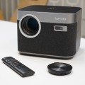
Inserisco questa,trovata in rete.EdoFede ha scritto:
Una foto dei condensatori cambiati fin'ora
In foto sembrano la metà
Utile per testare elettrolitici senza dissaldarli dal circuito.
TESTING ESR OF ELECTROLYTIC CAPACITORS
--------------------------------------------------------------------------------
I recently found an easy and cheap way to test ESR (Equivalent Series Resistance) of
electrolytic capacitors, in circuit, that might save some people a lot of time.
It requires only an oscillosope and a simple signal generator.
I had an oscilloscope that I was trying to repair (Intensity control had little effect. Horiz sweep was only halfway
across screen at higher freqs. One power supply rail was too low and others were too high.)
and I had already checked every electrolytic capacitor in several/many different ways (all in-circuit),
and even compared each of the readings to those from an identical unit:
Powered off: Looked at signature from component tester (single-curve tracer) across each cap,
and from each end of cap to ground, did resistance check with DMM, did capacitance check with DMM,
checked resistance from each end of cap to ground. Powered on: Put scope across each cap,
and scope from each end of cap to ground, used DMM and measured DC and AC voltages across each cap and from each end of cap to ground.
I did find some bad caps (and some other bad components) and replaced them. But the problems were still there!
I had been wanting to order an ESR meter, but hadn't done it yet, and needed to get this scope repaired immediately.
I went to Sam Goldwasser's excellent repair-FAQ site, at http://www.repairfaq.org/ and found a GREAT method for testing ESR of capacitors
in-circuit that requires only a signal generator and an oscilloscope (and some cables), and had found and fixed the problem within about
ten minutes!! Here's what I did (This technique is basically directly from Sam's repair faq site):
I used a signal generator and an oscilloscope to set up what I now call an "ESR Scope":
At the output of the generator, I connected a BNC "tee" adapter. I ran one 50 Ohm BNC cable from the tee to a good (Tek 2465A) scope
(with a 50-ohm BNC terminator on the scope input). On the other side of the tee,
I connected another BNC cable that had alligator clips on its other end
(It might have been a 75 ohm cable; shouldn't matter too much?),
which I clipped onto the banana plugs of a set of cheap DMM-type probes.
(Terminator note: I used a Tektronix 50 Ohm "pass-through" terminator,
on the scope end of the BNC cable. But, you should also be able to use,
instead, another BNC "tee" on the scope input, with an "endcap" terminator on one side and the cable coming in on the other side of the tee.
A standard 10BaseT Ethernet 50 Ohm coax terminator (and 50 Ohm Ethernet BNC coax cables) should work fine.
And they're available at Radio Shack, and probably Staples, et al.)
I set up the signal generator to produce square waves at about 100 kHz, with about 100 mv peak-to-peak amplitude
as seen on the attached scope, and no DC offset (A simple 555 timer circuit would do the job, too!).
Then, I turned the scope's v/div to 5 mv/div, with time/div at 1 microsec, with AC coupling of the input.
Shorting the probes together gave me a display on the scope that was about one division high.
It was basically a square wave, with large narrow peaks at each leading edge. But I only looked at the horizontal part's p-p amplitude.
That's the whole setup! No resistors. No nothing. Just cables (and a terminator).
I did also try it with a decade resistor box in series with the probes,
just to see what it would look like. I could clearly see each one-ohm increase, on the scope display,
with the probes shorted together as well as with the probes across a good electrolytic capacitor.
When I applied the probes across a GOOD capacitor in-circuit, there was little, if any,
change in the scope display, compared to when the probes were shorted (since, depending on the frequency,
a capacitor should look more-or-less like a short circuit, to AC).
But, when I tried it across a BAD capacitor, usually the display would be almost-totally off the screen.
And, there were some caps that looked marginal, making the display go from about one div p-p up to about 3 to 5 divs
(which probably corresponded with somewhere between 5 ohms and 20 ohms of ESR, if I recall correctly.)
Anyway, within just a few minutes I had found one more bad electrolytic filter cap in the power supply,
two smaller bad electrolytics in the P.S., a bad one on the horizontal sweep switch's board,
four bad ones near the middle of the main board, and a couple more that I can't remember right now.
I made a note of each one. When I was all done checking, the first thing I did was replace the filter cap in the power supply,
and then power it on and check the power supply rails' voltages. BINGO!!!!! YESSS!!! They were all normal again!
Not only that, but the horizontal sweep problem and the Intensity control problem were both GONE!! Yippee!
That filter cap had checked out as perfectly OK, using every one of the other methods that I described above
(all were "in-circuit", though), and compared OK to the other identical scope's same cap,
in all of those cases. But with this "ESR Scope" method, it was totally obvious, immediately.
And the same cap on the other scope tested good, with this method
(So, the earlier comparisons WERE bad cap vs. good cap, but showed nothing!).
[I also noted that after the bad cap was removed, it tested bad in the same way that it had while it was in-circuit, with
a basically identical scope display. And all of the other ones that I replaced also tested bad, when OUT of the circuit,
even with the other methods.]
This " ESR Scope " method isn't a perfect panacea, of course: There were some cases where,
without an identical unit to compare to, the displays would have been difficult for me to interpet,
and possibly misleading. (However, it *always* worked with every *electrolytic* that I tried it on,
IIRC, from 10 uF 10v to at least 1000 uF 100v, with no need for an identical unit to compare to.)
But, then again, I haven't played around with it enough, yet, either.
I assume that adjusting the frequency for different capacitances might be helpful, especially if non-electrolytics were to be tested.
I also seem to remember that a DC offset in the signal is usually used, when testing ESR.
I'll try that, later. And maybe increasing the amplitude of the square wave would be useful, sometimes, too.
But, usually, I think I'll want it to be low-amplitude, probably less than +/- 0.4v, so the signal doesn't turn on any semiconductor
junctions.
Well, that's it! I hope that this can save some of you some time, sometime...
Tom Gootee
tomg@fullnet.com
http://www.fullnet.com/u/tomg (Good used Electronic Test Equipment)
Mauro
-
04-02-2005, 20:35 #115
Senior Member
- Data registrazione
- Jan 2003
- Località
- Cambiago
- Messaggi
- 211
EdoFede ha scritto:
Una foto dei condensatori cambiati fin'ora
In foto sembrano la metà
Spaventoso!
Complimenti!
-
06-02-2005, 20:19 #116
Senior Member
- Data registrazione
- Aug 2003
- Località
- Fombio (Lodi)
- Messaggi
- 515
Oggi ho fatto le prime schede a doppia traccia; nell'ordine:
L; DE, DD. La situazione è molto meno critica di quello che pensavo.
Nessuno ha azzardato con la DA ?
Guardando le schede ho poi notato un sacco di check point e di bei trimmer; con un bel oscilloscopio mi sa che si può fare una bella taratura fine ...Un tipo come me si incontra una volta sola ... se hai sfiga due !
-
22-08-2005, 15:49 #117
Senior Member
- Data registrazione
- May 2002
- Località
- ROMA
- Messaggi
- 151
ciao EdoFede,
ho letto il tuo interessantissimo post sui condensatori e vorrei chiederti un parere su un problema che ho col mio 1270.
Per non duplicare il thread ti rimando a quello che ho aperto per chiedere aiuto:
http://www.avmagazine.it/forum/showt...threadid=33124
Grazie
ciao, MarcoStanco dell'infinitamente grande e dell'infinitamente piccolo, lo scienziato si dedico' all'infinitamente medio.
-
26-10-2006, 21:45 #118
Advanced Member
- Data registrazione
- Apr 2003
- Località
- Reading, UK
- Messaggi
- 3.285
Una domanda
Oggi ho quasi finito la E del mio bestione. Stavolta dovrei vedere qualche risultato!
Per i senza polarità un mio amico mi ha fatto prendere i plastici. Nessun problema salvo quello, mi pare, da 47uF che è un bisonte e non entra, ho dovuto fare una prolunga!
Ma voi i condensatori senza polarità elettrolitici dove li avete presi? Io ho preso tutto alla Farnell...
Ciao
A
-
27-10-2006, 07:46 #119
Advanced Member
- Data registrazione
- Dec 2004
- Località
- Bologna
- Messaggi
- 2.236
La prolunga può essere più dannosa del condensatore originale se è più lunga dei reofori del condensatore stesso.. ocio Originariamente scritto da Tony359
Per i 3900uF io ho lasciato quelli originali. Non c'è stato verso di trovarli e cmq non penso che cambino il mondo..
-
27-10-2006, 09:02 #120
Advanced Member
- Data registrazione
- Apr 2003
- Località
- Reading, UK
- Messaggi
- 3.285
Beh, la prolunga non è di 10cm... Giusto due pezzi di reofori di altro condensatore saldati sui piedini del plastico per poter "stringere".
Te cosa hai usato?
Ciao
A


